Proof of Concept RF Backscatter Communication Device
Motivation
Radio frequency back scatter devices (also known as retro-reflectors) were first popularized by “the thing” back in the 1940’s. Invented by Leon Thermin (of the Theremin instrument ), “the thing” was a covert listening device which functioned by modulating radio frequency signals when audio waves hit it. These devices typically consume increasingly little power (on the order of micro watts) since they only need to modulate RF signals rather than transmit them. In practice this means the device either allows ambient RF to pass through an antenna or passes a weak electrical signal through the antenna. This process only requires a single transistor and an antenna.
Sounds simple right? In theory, yes! I have found that the practice however is riddled with engineering challenges.
My goal with this blog post is to outline a device which is as simple as possible to construct and demonstrate the principles of RF backscatter communications. Hopefully this will help others get started with these techniques.
Parts List
Before we dive too deep, here is a list of the electrical components you’ll need to follow along at home:
- SKY65050 RF Transistor
- 20ish Ohm Resistor (I used a 22 Ohm)
- 1uF capacitor
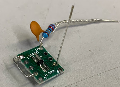
- 1inch of wire (for creating the antenna)
- SOP 10 .5mm breakout board (This is optional as you could totally solder this all point-to-point with no PCB)
Additionally I’ll be utilizing the following equipment:
- Regulated Bench DC Power Supply (Anything capable of supplying +3VDC @20mA will suffice)
- Arbitrary function generator (Anything capable of producing a 0v-5v 100Khz-5MHz square wave will suffice)
- Oscilloscope (Optional but helpful for debugging)
- Two HackRF One SDRs
- Two 2.4Ghz Antennas (You can borrow some wifi antennas off of a wifi router or order some directional high gain antennas from amazon. I recommend this log periodic antenna )
Backscatter Communication Architecture
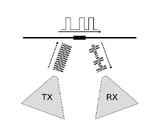
Typically backscatter sensors require a radio transmitter and a radio receiver. The transmitter sends energy towards the sensor in the form of radio waves. The sensor then modulates these radio waves and in the process some of these waves are scattered back towards the radio receiver. Fortunately for modern engineers such as ourselves, we have software defined radios which can handle both the transmitting and receiving radio tasks! For the purposes of my demonstration, I’ll be using two HackRF’s. While these SDRs aren’t quite cheap, they are at least readily available for purchase.
Circuit Schematic
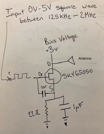
As always, I’d recommend doing a quick read through of the SKY65050 data sheet . As far as data sheets go, I found this one in particular to be quite helpful and pretty straightforward to read. It’s important to note several things mentioned in this data sheet, and we can learn a lot from the provided schematic of the SKY65050 evaluation board. That being said, there is also a lot of information in this data sheet which we can safely ignore for now since we aren’t trying to actually achieve this device’s full specs of capability for RF switching. Of particular note: -If we’re thinking of this device/transistor as a switch, the analogy would liken this SKY65050 to a normally closed switch. That means, when no signal is applied to the gate of the transistor, the device allows current to flow from drain to source (and vice versa I believe?) -Typically this transistor wants to be negative biased which would require us to apply less than or equal to -3V to the gate in order to open the switch and prevent current from flowing between the drain and source -The requirement for a negative voltage gate drive signal can be eliminated with an appropriate resistor and capacitor wired in parallel with each other and connect between one of the SKY65050’s source leads and ground (this is described at the bottom of page 2 in the data sheet) -While both the data sheet and my hand drawn schematic above call for a capacitor to be placed between the gate and source of the SKY65050. The data sheet specifies that this capacitor value is supposed to be .1pF. Since .1pF is such a tiny capacitance value, I just totally omitted it and connected the gate and source directly together with a small jumper wire. (I think this capacitor is normally there for impedance matching. If we were really engineering for super high efficiency, we’d probably think harder about including it but for our purposes omitting it seems to work just fine)
Supporting Equipment
3 Volt 0.02A Power Supply
In practice, pHEMT RF switches like the one we’re using can be engineered to switch without a voltage applied to their drain. For the purposes of our demo, we’re applying 3volts with a current limit of 20mA to the drain of the SKY65050. This small voltage is utilized to make the self-biasing scheme work that the switch’s data sheet recommends. You can use any 3v power supply you like but a regulated bench supply is one less thing to debug if things aren’t going to plan.
Frequency Generator
While normally you’d want a backscatter sensor to actually sense something, for the purposes of this demonstration we’d like to utilize a known fake sensed signal to aid in our inevitable debugging efforts. This known signal will be a 5v high peak, 0v low peak square wave generated by a frequency generator. Square wave frequencies between a few KHz on up to several MHz should all work just fine. As you can see above, I’m utilizing a bench top arbitrary function generator. While you could easily also use a micro-controller’s digital output or 555 timer IC to generate a square wave with appropriate frequency and amplitude, the bench top function generator is one less thing to debug if the device isn’t behaving as expected.
Oscilloscope
While an oscilloscope is not absolutely required for this demonstration, I’d recommend utilizing a scope which can sample at the frequency (er, double the frequency because Nyquist, but you get my point) of the square wave we’re applying across the gate of the SKY65050. Again, in our case that’ll be a range between several KHz to several MHz. Most ‘scopes should be able to handle this sort of task. By utilizing a oscilloscope we can directly probe the antenna attached to the backscatter circuit. Ideally you’ll see this antenna oscillating at the same frequency of the applied square wave from the function generator.
GNU Radio Flow graph
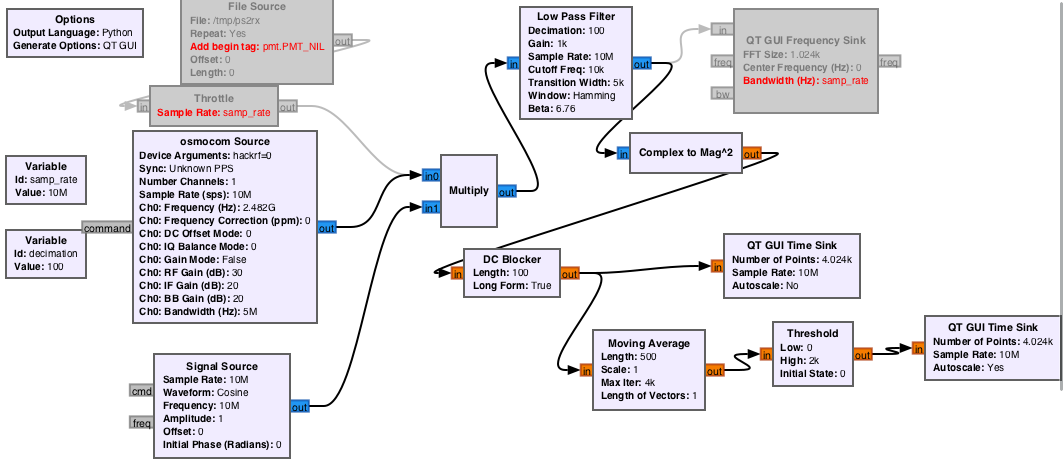 I was able to successfully use Michael Ossmann’s CONGAFLOCK gnuradio flow graph file to get this experiment working. There were however a few notable hiccups along the way. I’m attaching the above image as a reference for how things in this flow graph should look but your setup may differ slightly based on how your versions of gnuradio, osmosdr, and python are installed.
Here are a few of the hiccups I encountered and some brief notes on getting around them:
I was able to successfully use Michael Ossmann’s CONGAFLOCK gnuradio flow graph file to get this experiment working. There were however a few notable hiccups along the way. I’m attaching the above image as a reference for how things in this flow graph should look but your setup may differ slightly based on how your versions of gnuradio, osmosdr, and python are installed.
Here are a few of the hiccups I encountered and some brief notes on getting around them:
- For some reason, I was not able to successfully save the file directly from github and then have it work in gnuradio (upon trying to load these files, gnuradio would spit out a bunch of python parsing errors). I found that viewing raw, selecting all, copy and pasting into a empty file, and then saving as a .grc file resulted in a file which would successfully load into gnuradio
- Once I was able to successfully load the grc file into gnuradio, I found that gnuradio was unable to properly load several of the flow graph blocks due to my installation utilizing Py QT (versus Michael Ossmann’s using WX GUI). This was rectified by going through these blocks one by one and manually replacing them with their Py QT equivalents.
-
Finally, my last hurdle was figuring out how to utilize two HackRF One’s on a single computer: The key to this relies on the hackrf_info command from the hackrf command line tools and device arguments field in the osmocon Source block utilized in the gnuradio flow graph. Here are the steps I used:
- Before running any of the gnuradio flow graph stuff, plug both HackRF SDR’s into your computer
- Pop open a terminal and run the $hackrf_info command
- Take a note with the device serial numbers (hopefully hackrf_info will list both a device 0 and device 1)
- Now open the rr-ps2.grc file from Michael Ossmann’s github and double click the osmocon Source block to pop open its propteries window
- In the device arguments field, enter: “hackrf=0”
- This will configure the gnuradio flow graph to utilize the first hackrf plugged into your system.
- You can now run this gnuradio flow graph and it will put one of your HackRF One to work as a reciever.
- To utilize your second HackRF one as a transmitter for this experiment, pop open a terminal window and run the following command: $hackrf_transfer -s 2000000 -a 0 -x 30 -c 64 -f 2482000000 -d [insert the serial number for the second HackRF you found with the hackrf_info command earlier]
This should hopefully give you all the tools and tips you need to recreate my work!
Demonstration Experiment
Open Questions
- According to folks who have recreated Michael Ossmann’s NSAPlayset CONGAFLOCK RF retro-reflector, the 2N7000 transistor should be able to backscatter RF. I tried to recreate their circuits to no success. While I know the 2N7000 cant actually switch at a rate of 2.482GHz, this shouldn’t matter since we are only requiring the tag to switch at 10khz - 500khz. I wonder if perhaps the 2N7000 can’t actually pass the 2.482GHz signal between drain and source while the gate is powered on?
- The SKY65050 data sheet mentions that the transistor’s gate should be attached to 0v in order to make the biasing work but in the provided schematic of the evaluation board, the source and gate are actually connected to each other via a capacitor. I think I’m misunderstanding exactly what capacitor C3 is doing between the source and gate. Do I need C3 in my circuit? Should I disconnect source and gate from each other?