Atomic Puppy 3lb Battle Bot
 As a kid I was an avid fan of the battlebots TV show and when I first started hanging out at the GaTech Invention Studio, I was really excited to meet people who were actually building their own battle bots. After hanging out at a few battle bot competitions, I decided to attempt building my own. While building a battle bot had been on my to-do list for almost three years, I continually found it difficult to set aside enough time to actually design and build a robot that I could compete with. This year at DragonCon however, my buddies Xo Wang, Aaron Fan, and Mat Carroll told me I should build a robot for Motorama 2015 robot wars.
………fast forward to the weekend of February 6th 2015….
I waited until early February to actually begin working on my robot and this was an issue for several reasons:
- battle bots take time to design and build (often quite a lot of time to build a very nice battle bot)
- I was living in San Francisco where my only reasonably accessible machining resources were limited to 2 small consumer grade ABS 3D printers and a Roland MDX-40 CNC mill in the Google Garage
- I was working at an internship that required me to work 40 hours a week (so I’d have to build the bot after work on weekdays)
Not fully realizing the challenges that were ahead and full of childlike excitement, I began designing my robot.
Due to my machining and time constraints, I decided to keep this robot as basic as possible using easy to machine materials and as many off-the-shelf components as possible. These design decisions led me to a beetle weight (3lb) vertical spinner robot which utilized a 4.5″ circular saw blade as its weapon and .5″ Ultra High Molecular Weight (UHMW) polyethylene sheet as the primary frame material. Since the design was inspired primarily by Charles Guan’s Nuclear Kitten IV robot, I settled on the name Atomic Puppy and began Computer Aided Drafting (CAD-ing) (logically I had to pick a name before CAD-ing so I knew what to base the design file names on).
Robo-CAD
I used the SolidWorks CAD program to design all of the robot parts that I would need to manufacture. This began with frame rails, and then the weapon and drive train components. To ease construction and maximize serviceability, I decided on a frame design that would be held together using 10mm outside diameter M6 threaded rods of varying lengths. From there on, it was basically a “plug and chug” operation. I measured my wheels, drive motors, and weapon components then designed a modular frame to fit all the components. By the end of Saturday night, I had all of my designs completed and my parts were ordered from McMaster Carr.
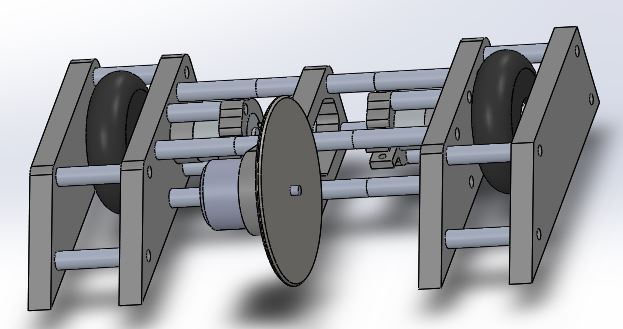 The finished CAD assembly of Atomic Puppy
Electronics
In keeping with the decision to use simple, off the shelf components, my electronics were as follows:
- Drive Motor Controllers: Vex-trollers
- Weapon Motor Controller: Hobbyking 50amp 3-phase brushless ESC
- Control Electronics: Hobby King 6-channel RC transmitter and receiver
- Batteries: 3S 1000mAh lipos
- Drive motors: 1000rpm 12v gearmotors
Manufacturing
As mentioned above, I used the Google Garage for all of the parts manufacturing for this robot. Google may have a lot of perks, but my favorite by far is the Garage which is a little hacker space for Googlers (Google also has some really nice machine shops but those are limited to full time employees due to insurance reasons infinite sadness ). Anyways, I coaxed my buddy Xo into showing me the in’s and outs of the Roland MDX-40 CNC router and began generating toolpaths for all of my parts using a CAM plug-in for SolidWorks called HSMworks. Once I had a few parts tool pathed, we spent the entire presidents day holiday determining optimal cut settings through a series of test cuts.
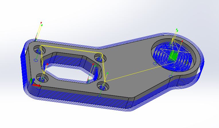 The tool-path for milling the weapon frame plate.
SIDE NOTE : UHMW is an awesome material but has some characteristics which make it particularly difficult to machine cleanly on the Computer Numerically Controlled (CNC) milling machine that I had access to. For instance, the Roland MDX-40 has a minimum spindle speed of 4500 rpms (which is incredibly high compared to most other CNC mills which typically go down to the 600’s for materials like stainless steel). Such a fast spindle speed means that while machining plastics (like for instance, UHMW), things are going to have a tendency to melt. To counteract the material’s inclination to melt, it is a good idea to pick an end mill with as few flutes as possible and cut at a fairly quick rate. The reasoning behind these two techniques is to essentially remove as much of the energy imparted into the material by the machine as possible through chips. Cutting fast with a small number of flutes and a slow spindle speed will typically be the easiest way to cut properly because large chips are formed and then are immediately cleared from the stock material so as not to heat the stock to the point of melting. If you’re able to cut UHMW without melting it, the resulting machined surfaces tend to be smooth and highly dimensionally tolerant. I settled on a spindle speed of 4500rpm, a cutting speed of 400mm/min, and used a 1/4″ diameter 2-flute end mill.
Since I was running very short on time (only a few days out from the competition), I for some reason decided that it would be a good idea to 3D print the hubs that would connect my 2.5″ diameter fly lite wheels to the drive motors (boy was I wrong!). I removed the stock ABS hubs from the wheels using brute force and ignorance, used calipers to measure the dimensions of the stock hubs, and then designed my own hubs which had a shaft collar on the end to allow the hub to connect securely to the drive motors. While I had no trouble actually printing the hubs on the Garage’s Up! Plus 2 printer, I discovered that the hubs weren’t entirely straight. When I test fit the hubs, they fit onto the motor shafts really well but, because they weren’t staright along their center axis they caused the wheels to rotate in a fashion that was highly cattywampus.
Assembly
Most of the assembly time was spent threading the 10mm OD 5.3mm ID aluminum rods with M6 threads through both ends. I spent one afternoon threading all 48 holes by hand (it wasn’t much fun). After all the rods were threaded, it was simply a matter of putting each rod between two frame rails and then bolting it in on both sides using a steel M6 screw. By the Friday morning (somewhere in the neighborhood of 3am) that we were scheduled to fly to the competition, I had the frame completely assembled with all the motors attached. Once we got to Harrisburg PA, I needed to finish the bot before the following day’s competition and was running on a full two hours of sleep so I decided it’d be a great idea to stay up all night and finish the assembly. It was at this point that I test drove the robot and realized just how terrible the 3D printed hubs were. After much consideration, I just decided to epoxy them onto the motor shafts in the straightest configuration possible. Fortunately my friend Gabe Ocha was around and he epoxied the wheels on while I finished soldering up the electronics. While the epoxy dried, I took a quick nap. The morning of the competition, I test drove the bot for the first time and was overwhelmingly happy that I’d actually had a completed bot to compete with.
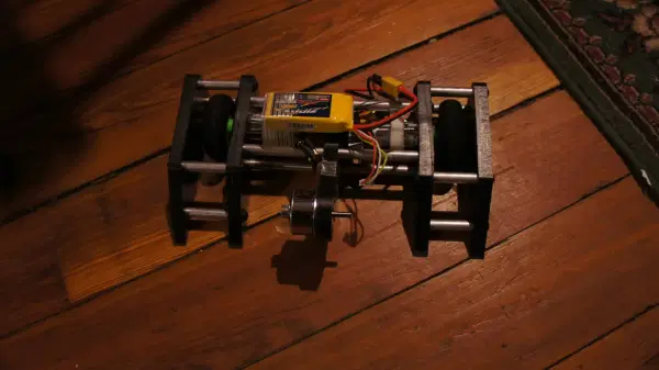
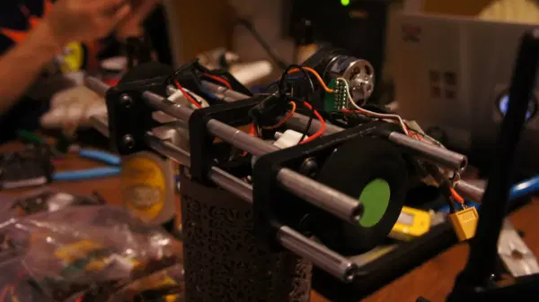 Things are starting to come together in this picture. You can see that the electronics are mostly in the frame, the 3d printed wheel hub has been epoxied onto the motor, and some of the threaded rods have been mounted.
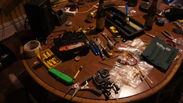 Our makeshift workbench at around 3am the night before Motorama.
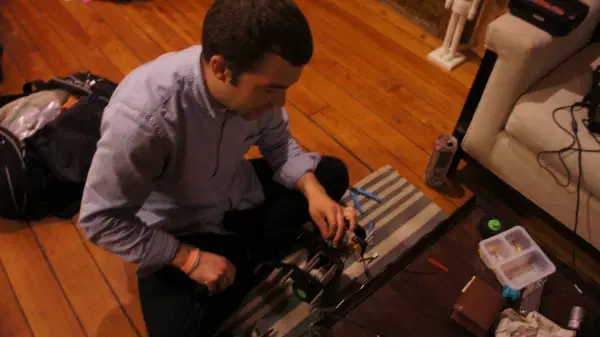 Soldering the electronics up on the floor of our Airbnb
 The first test drive!
Competition and Final Thoughts
At the competition, I quickly discovered that the prop adapter I used for attaching the blade to the weapon motor was the Achilles heel of my robot. In both of my two matches I lost because when I hit the opponent with my blade spinning at full speed (~10k rpms), the prop adapter would just pop off and I would loose my weapon. For example, I lost my first match because during the first hit I got on the other robot, my blade went flying and I was left defenseless. Fortunately in my second match I was able to do some damage to the other robot before my blade popped off but ultimately the damage I did wasn’t enough for the judges to declare me the winner and so after losing two matches, I was eliminated from the tournament.
Although I didn’t win any matches, I still consider the weekend a monumental success. First of all, my robot is going home in fully operational condition despite taking many hard hits during the competition. I’ll be able to make a few small upgrades and the bot will be ready for more battles! Second, I’m so happy to have gotten to become more familiar with the CNC milling workflow and the fact that I was able to construct the robot in a week amazes me. Finally, I got to spend the weekend traveling and competing with some of the greatest engineers I know (plus, there was even some snow drifting in a waffle house parking lot!) so, post-competition I am one happy dude.
I’d like to thank all of my friends who encouraged me to finally build a robot and also those who took time out of their crazy busy schedules to help make a dream of mine a reality.